Converting a Tasmota smart plug to ESPHome

A photo of a Coosa smart plug, originally running Tuya firmware, and a USB to UART converter. This now runs ESPHome firmware.

Back in June, I flashed some old Tuya Wi-Fi smart plugs with Tasmota firmware. I’ve now re-flashed one of them with ESPHome, an alternative firmware by the Open Home Foundation who are the same people as Home Assistant. In this blog post, I’m going to outline:

  • Why the change from Tasmota to ESPHome
  • How to build a YAML file for ESPHome
  • The flashing process

This is a longer blog post, so if you want to skip the explanations for each section of the YAML file and just want to go ahead and do this yourself, you can download my pre-made YAML file from GitHub, and then follow these instructions.

Why the change from Tasmota to ESPHome

If you’re starting out with custom firmware for your existing devices, then I would still recommend Tasmota. It’s much easier to set up, as you install it first, and then configure it. There’s also a much more extensive repository of supported devices, so you shouldn’t need to do much manual tinkering once Tasmota is installed.

ESPHome, by contrast, requires you to configure it first, and then install it. Furthermore, rather than offering a web interface for configuring your devices, instead you have to do this in a YAML file. And then you have to compile the firmware specifically for your device and upload it.

That being said, ESPHome is much more powerful. You can build automations into it that run on the device itself, rather than through, say, Home Assistant. And as each firmware binary is compiled for each device, it’s much smaller, which allows for easier updates. On some Tasmota devices, you have to install a ‘minimal’ version of the firmware before you can upgrade. By contrast, with ESPHome, your device should be able to update directly to new firmware versions.

As you would expect, ESPHome integrates better with Home Assistant. Indeed, one reason for me changing to ESPHome is that the Tasmota integration takes a while to start up and is one of those slowing Home Assistant down. Firmware updates are also offered through Home Assistant, so you don’t need something like TasmoAdmin to manage firmware updates for multiple Tasmota devices.

Building the YAML file

I’m going to go through each section of the YAML file, to explain what it does, and why it’s necessary. Some of these are specific to the plugs that I’m using, and may not transfer to other devices.

Firstly, with Tasmota still running, open the Configuration screen and choose Template. This will give you a list of the GPIO pins, and what they currently do in Tasmota. You’ll need to note these, so that you can tell ESPHome what pins to use. On mine, these were the ones in use:

  • GPIO4 – LED
  • GPIO5 – Relay
  • GPIO13 – Button

The LED is the light on the smart plug, the relay is what controls whether the power is on or not, and the button is the physical button on the smart plug that controls the relay. Whilst the relay is the most important, to preserve the device’s full functionality, we need to tell ESPHome about all of them.

The ESPHome section

Here’s the first bit of the YAML file:

esphome:
  name: $name
  friendly_name: $friendly_name

esp8266:
  board: esp01_1m

If you use the wizard in the ESPHome Device Builder, then these will have been created for you and filled out with whatever name you’ve chosen. The second block tells ESPHome that the device has an ESP8266 chip, and it’s a generic board. This was the default selection and seemed to work fine for me.

Logging, API, OTA, Wi-Fi

Next, we have the following:

# Enable logging
logger:

# Enable Home Assistant API
api:
  encryption:
    key: $key

ota:
  - platform: esphome
    password: $password

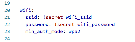
wifi:
  ssid: !secret wifi_ssid
  password: !secret wifi_password

  # Enable fallback hotspot (captive portal) in case wifi connection fails
  ap:
    ssid: "esphome-smartplug"
    password: $fallbackpassword

captive_portal:

The logger means that the device will keep logs. It’s up to you whether you keep this in, but as I was coming up with this myself, I decided it would be best to help debugging.

Because I’ll be using this smart plug with Home Assistant, we need to include the ‘api:‘ section. Again, the ESPHome device builder should have filled out an API key here.

The ‘ota:‘ section allows for ‘over the air’ updates. This means that your device can update to new versions of ESPHome without needing to be plugged in to a device, either over USB or a UART connection.

In the ‘wifi:‘ section, this includes references to the ESPHome Device Builder’s secrets file which should have your Wi-Fi network SSID and password. If the smart plug can’t connect using these details, then, as a fallback, it’ll create its own access point. This is where we also need the ‘captive_portal:‘ section, which allows the user to select a Wi-fi network if the one we’ve pre-programmed can’t be found.

Web server

Next, we have this section:

web_server:
  port: 80

This is optional, but it creates a Tasmota-like web app that you can connect to. This will allow you to press the button on the smart plug, view the logs, and upload firmware. We don’t need it, but it partially replicates the functionality of the previous Tasmota firmware, and helps with debugging.

Binary sensor

This is the section that enables the hardware button on the smart plug to work:

binary_sensor:
  - platform: gpio
    pin:
      number: GPIO13
      mode: INPUT_PULLUP
      inverted: True
    use_interrupt: True
    name: "Power Button"
    id: "smartplug_button"
    on_press:
      - switch.toggle: "smartplug_relay"
    disabled_by_default: True

We’re telling ESPHome that the button is attached to GPIO pin 13, and, when the button is pressed, to toggle the relay on or off. I’ve also added the ‘disabled_by_default: True‘ line so that it doesn’t show in Home Assistant.

Switch

Now, we need to configure the relay, and make it available to Home Assistant:

switch:
  - platform: gpio
    name: "Switch"
    id: "smartplug_relay"
    pin: GPIO5
    on_turn_on:
      - output.turn_on: led
    on_turn_off:
      - output.turn_off: led
    restore_mode: RESTORE_DEFAULT_ON

So, we’re telling Home Assistant that the relay is connected to GPIO pin 5. We’re also telling it to turn on the LED when the relay is turned on, and off again when it’s turned off. The ‘restore_mode: RESTORE_DEFAULT_ON‘ tells ESPHome what to do when the device boots up, perhaps after a power cut. I’ve set it to try to restore the status that it had before, but if it can’t, to turn the relay on.

LED

Here’s our final block, to tell ESPHome that there’s an LED

output:
  - platform: gpio
    pin: GPIO4
    inverted: true
    id: led

Again, we tell ESPHome that it’s connected to GPIO pin 4. The YAML code in the Switch section tells ESPHome when to turn the LED on or off.

So, now we have a YAML configuration file. This should be added as a new device in the ESPHome Device Builder.

The flashing process

The good news is that switching from Tasmota to ESPHome is easier than from the original Tuya firmware. You probably won’t have to get out a UART converter and cables, unless you accidentally brick your device. Instead, you just need to follow these instructions, which involve manually downloading the firmware binary, and then uploading it to Tasmota. When the device restarts, it’ll be running ESPHome instead.

Energy monitoring over Matter

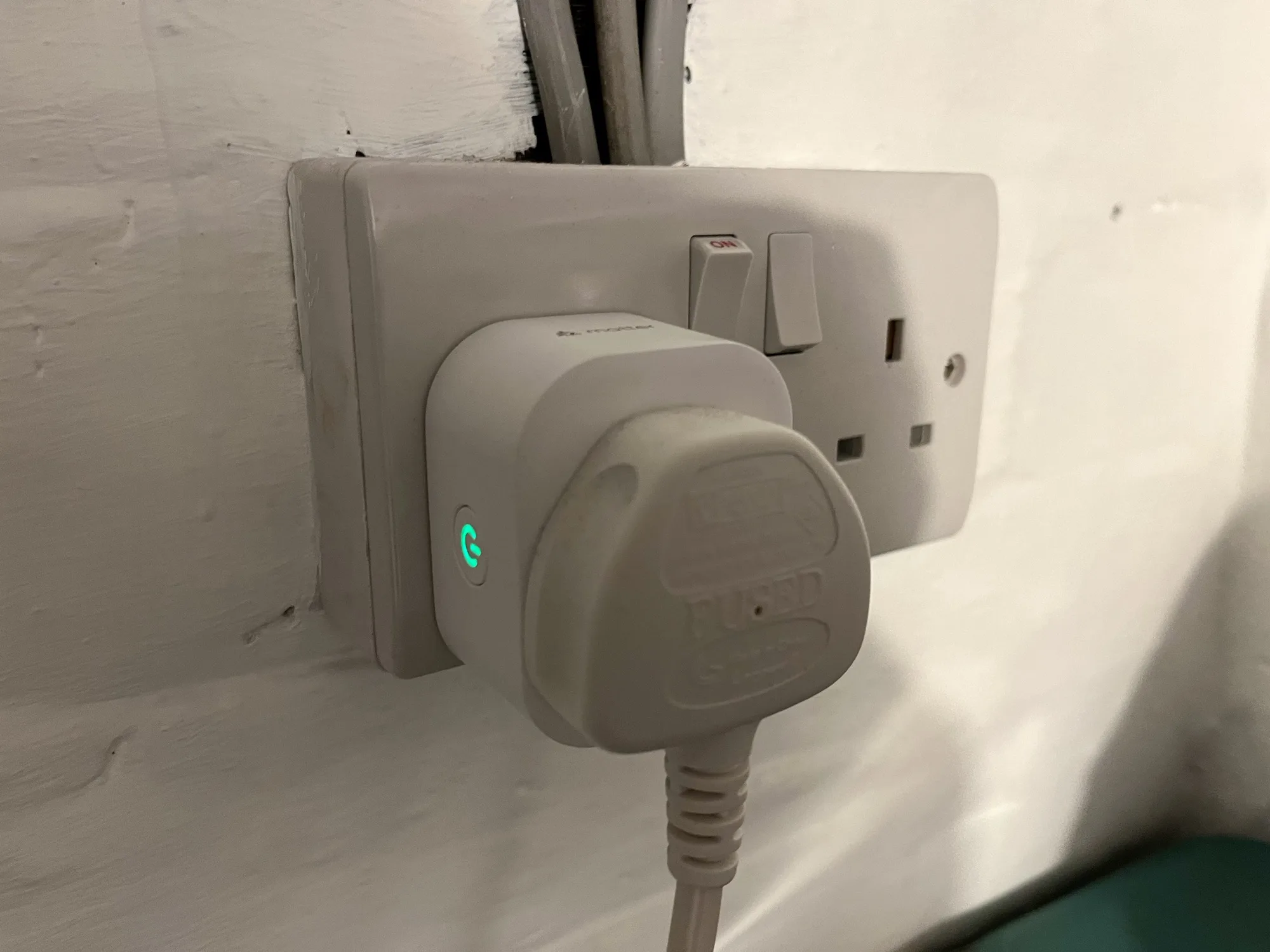
A photo of a Meross energy monitoring smart plug in a UK plug socket

Back in April last year, I bought a pair of Meross energy monitoring smart plugs (sponsored link). I’d chosen them because they supported Matter, and so could be easily added to Home Assistant, Google Home and Apple Home all at the same time. However, I lamented that their Matter support was limited to turning them on and off; the energy monitoring data wasn’t available through Matter. That has now changed.

If you have these plugs, or are looking at buying them, here’s how to get energy monitoring over Matter into Home Assistant:

Step 1: Update the Firmware

Firstly, you’ll need to open the Meross app on your phone, and ensure that the smart plug is linked to the app. Next, you’ll need to do a firmware update – this is located on the user tab, for some reason. The firmware update should take a couple of minutes.

A screenshot of the Home Assistant interface, showing the settings for the Meross energy monitoring smart plug and the 're-interview device' option.

Step 2: Re-interview your smart plugs

Originally, the way I found out that this was working was because one of my plugs had stopped working, and needed a factory reset. I then had to remove and re-add it to Home Assistant, Google Home and Apple Home. When I re-added it to Home Assistant, that was when I found that it now supported energy monitoring over Matter, as the power, wattage, voltage and current for the smart plug now appeared in the device settings.

The good news is that you don’t need to remove and re-add the device. Instead, you can ‘re-interview’ the device. Open it up in Home Assistant’s device settings, and then click the three dots next to ‘Share device’, and then ‘Re-interview device’. Home Assistant will then attempt to find out what capabilities the device has, and should add the new entities for you.

Step 3: Uninstall the Meross LAN custom integration

Now that Home Assistant can receive the energy monitoring data over Matter, you shouldn’t need the Meross LAN integration from HACS anymore. You’ll need to amend any existing automations that use the Meross LAN entities (I use this energy monitoring blueprint), and then remove the devices before uninstalling it through HACS. This was one of the integrations that was causing the biggest slowdowns in my Home Assistant, and it seems to be more responsive now that I’ve removed it.

The key advantage of using energy monitoring over Matter is that the data remains local to your home network. Otherwise, you’re sending and receiving data to Meross’ servers (unless you’ve managed to reconfigure them to use a local MQTT broker like Mosquitto). That also means that, if those servers go down or Meross withdraws support, you would no longer get energy monitoring data. Switching to Matter should therefore give your smart home system more resilience.

How to disable go2rtc in Home Assistant

Home Assistant includes support for go2rtc, a streaming video application, which can be used to monitor and store footage from CCTV cameras. Since the November 2024 (2024.11) release of Home Assistant, go2rtc has been included in Home Assistant’s Default Config, which means that integration is loaded automatically on startup. If you don’t have any cameras to monitor in Home Assistant, this can mean some warnings appearing in your logs, and potentially slow Home Assistant down.

There are two ways to disable go2rtc if you don’t need it – a hard way and an easy way.

Hard way: Disable Home Assistant’s Default Config

You can tell Home Assistant not to load the Default Config. This gives you more control over which built-in integrations are loaded when you boot Home Assistant up, however, it means editing your configuration.yaml file. You’ll need to delete the ‘default_config:‘ line, and then create new entries for all the parts of the default configuration that you want to keep. This may be fine for simple installations, but for most users, this will add more complexity. I wouldn’t recommend this personally.

Easy way: Using HACS integrations

There are two HACS integrations that you need to install:

  1. Early Loader
  2. Default Config Exclude

These are not in the standard HACS repository, so you’ll need to open HACS, click on the three dots in the top right, select ‘Custom Repositories’ and then add the Github URLs in turn. You’ll need to install Early Loader first, restart Home Assistant, and then install Default Config Exclude next.

Once installed, you’ll still need to edit your configuration.yaml file, but instead you’ll only have to add a small block. Here’s mine:

default_config_exclude:
  - go2rtc
  - stream
  - cloud
  - my

What you’ll notice is that I’ve added some other integrations – stream, Home Assistant Cloud, and My Home Assistant. If you don’t have any cameras, then not only do you not need go2rtc, you probably don’t also need stream either. I don’t use Home Assistant Cloud or My Home Assistant, so I’ve disabled these too. As well as starting up a little quicker, Home Assistant also now uses slightly less RAM than before.

Home Assistant Green review

A photo of a plugged-in Home Assistant Green

Since I started using Home Assistant in October 2023, I’ve been running it on a Raspberry Pi 4, first in ‘Container’ mode and more recently in ‘Supervisor’ mode. I’ve now bought a Home Assistant Green, and I’m using this to run Home Assistant.

The Home Assistant Green is one of the two dedicated hardware platforms that come pre-installed with Home Assistant. The other, the Home Assistant Yellow, deserves its own section later on. By buying one of these devices, you’re also helping to financially support the Home Assistant project.

Why I bought a Home Assistant Green

As someone who has previously gone down the DIY route, it may seem surprising that I’ve decided to buy a Home Assistant Green. My decision came down to the following:

  • Price – the Home Assistant Green costs around £90 in the UK, which isn’t much more expensive than a bare bones Raspberry Pi 5. Once you’ve added a case, power supply and SSD to a Raspberry Pi, the Home Assistant Green is actually cheaper.
  • Cheap to run – I had considered some kind of mini PC, which would offer me more power, but with both a higher upfront cost and ongoing electricity cost. The Home Assistant Green runs on up to three watts; it comes with a 12 volt, one amp barrel plug power supply. As it’ll be on all the time, I don’t want a power-hungry device.
  • The need for a dedicated Home Assistant device. In May, it was announced that the ‘Supervised’ install method would be deprecated along with ‘Core’; only a tiny fraction of people use these methods. This dovetailed with me wanting a dedicated device for Home Assistant, rather than trying to run it on the same little Raspberry Pi as Plex and some other services. In other words, I was in the market for an additional device to run Home Assistant, and the Home Assistant Green fitted the bill. Meanwhile, my Raspberry Pi 4 can be dedicated to Plex.
  • No longer needing to worry about compatibility. According to Home Assistant Analytics, over a third of people install Home Assistant on a Raspberry Pi and so I don’t expect it to become unsupported. However, as the Home Assistant Green is the closest thing to ‘official’ hardware, I know it’ll be well-supported in future releases. As I’m coming to rely on Home Assistant more, I need it to run on a reliable platform.

What the Home Assistant Green can’t do

Coming from a Raspberry Pi, it’s worth noting what features the Home Assistant Green lacks. These include:

The Home Assistant Green does have two standard USB-A ports for you to plug in dongles and hubs, so I have my Thread and Zigbee dongles connected. Not having Wi-Fi or Bluetooth on board may reduce interference on the 2.4 GHz band, I suppose.

The box that the Home Assistant Green comes in

Home Assistant Green hardware

The Home Assistant Green is actually bigger and heavier than I expected it to be – certainly, it’s larger than a Raspberry Pi. It has a very sturdy base, which is designed to act as a heat sink – it’s passively cooled so there’s no fan noise. Inside, there’s a quad-core 1.8 GHz ARM processor, placing it between the Raspberry Pi 4 and 5 in terms of computing power. There’s 4 GB of RAM, and storage comes courtesy of a 32 GB eMMC (embedded multimedia card).

You’ll also get an AC adaptor with a variety of plugs (including a UK 3 pin plug) and an Ethernet cable.

Optionally, you can install a CR2032 battery inside. It doesn’t come with one, but if you add a CR2032 battery then the system clock will remember the time between reboots. It’s mostly only needed if you’re using it somewhere with poor or no internet access, as otherwise the clock synchronises with the internet on startup.

There’s also an HDMI port and a slot for a micro-SD card, but these are only for system recovery purposes and not for general use.

I would tell you more about how it is to use, but to be honest, it’s just like using Home Assistant on any other platform. All I had to do was restore a backup from my Raspberry Pi 4, and I was up and running.

Home Assistant Yellow

If the Home Assistant Green doesn’t meet your requirements, consider the Home Assistant Yellow. It’s more advanced and upgradeable, but also requires some assembly as it ships without a logic board. That’s provided by a Raspberry Pi Compute Module, the idea being that you can upgrade this incrementally over time without needed to buy a whole new device. It’s a nice idea, but it also adds to the cost – the base Home Assistant Yellow costs around £120 with the Compute Module adding £30-40 on top, and it arrives in kit form rather than pre-assembled. However, long term, it could be cheaper due to it being upgradeable.

There are other differences: The Home Assistant Yellow is available with Power over Ethernet (PoE), meaning that it doesn’t need a separate power supply. However, you’ll need a router or a switch which supports this. If you don’t, then you can buy a Home Assistant Yellow with an AC adaptor.

The Home Assistant Yellow also has an 802.16 radio, meaning that it can support Zigbee devices without an extra dongle. This can also be re-programmed to support Thread, but not both Thread and Zigbee at the same time. Additionally, there’s a 3.5mm audio port, and inside, there’s an expansion port for installing an SSD if you need one.

Whilst I have the technical knowledge to get a Home Assistant Yellow up and running, once you’ve factored in everything, it costs about double the price of a Home Assistant Green.

Ditching proprietary Zigbee bridges

A photo of two dongles, both Sonoff ZBDongle E devices, labelled 'Zigbee' and 'Thread'.

For my Zigbee devices, I use Zigbee2MQTT and a Sonoff USB Zigbee dongle as my co-ordinator. As I came quite late to the Zigbee party, I didn’t pick up a proprietary Zigbee bridge, but if I had, I wouldn’t use one. Today, I’m going to go through a few reasons why.

Examples of proprietary Zigbee bridges include the Philips Hue Bridge, the Ikea Dirigera Hub and the Tuya Zigbee gateway, but there are others. Here are my reasons why it’s best to go with a more open system, like Zigbee2MQTT or Home Assistant’s Zigbee integration. I’ve previously compared the two.

A map of my Zigbee network, showing the mesh connections between devices

Having all your devices on one Zigbee network

Zigbee is a mesh network. That means that, as more devices are added, the network actually gets stronger, as each device can communicate with each other. This is especially true with mains powered Zigbee devices like smart plugs and light bulbs. Therefore, if all of your Zigbee devices are on the same network, the connection between each device should be stronger. I’ve included a diagram of my network above, and you can see the multiple mesh connections between devices.

If you have multiple Zigbee bridges – say one for your Hue lights and another for your Ikea smart plugs – you risk causing interference between networks. Furthermore, Zigbee runs on the same 2.4 GHz frequency band as Wi-Fi, Bluetooth and your microwave oven. Having everyone on one network should reduce interference.

Better device support

Some Zigbee bridges are better than others, when it comes to supporting third-party devices. For example, you might be able to add an Ikea Tradfri bulb to a Philips Hue bridge, but possibly not another kind of device. Zigbee2MQTT has, arguably, the best device support and will work with just about any Zigbee device, regardless of manufacturer. You can check the Zigbee Device Compatibility Repository to see which devices work with which platform.

My Zigbee devices are a mixture of Tuya and Ikea, and they co-exist well within Zigbee2MQTT.

Cheaper

Most proprietary Zigbee bridges cost around £60. Meanwhile you can plug a USB Zigbee dongle into a spare PC, or a low-powered Raspberry Pi device that you may already have. The USB dongles typically cost £20-30 each (my Sonoff ZBDongle-E costs £27 at Amazon at present [sponsored link]), and you’ll only need one dongle and one computer rather than multiple bridges.

Easier to troubleshoot

With both Home Assistant’s ZHA and Zigbee2MQTT, you can look at the logs to see what’s going on inside your Zigbee network. Hopefully, that’ll help with troubleshooting any devices that aren’t working the way they should. As shown above, you can also get a diagrammatic representation of your network. This lets you see how your devices connect to each other and whether there are any weak spots on your mesh.

Not reliant on cloud services

There’s a risk that your proprietary Zigbee bridges could become expensive paperweights, if their manufacturers decide they’re no longer going to support them and turn off the cloud servers. They may continue to work locally, but if their cloud servers go dark, you may find that you can’t control your devices remotely any-more. By hosting your own Zigbee bridge, you can still have remote access but on your own terms. I use Homeway for remote access to Home Assistant, but you can also set up your own reverse proxy, for example.

Proprietary bridges may offer some convenience and a nice app, But, if you’re willing to put a bit of effort in to manage your Zigbee devices yourself on one single network, I think there are more advantages of going down the route of using Zigbee2MQTT or ZHA.

Zigbee PIR motion sensor

A photo of a Zigbee PIR motion sensor

Regular readers may be relieved to know that I’m done writing about my trip to Athens, and are back to the occasional series of ‘Neil reviews cheap Zigbee devices from AliExpress’.

Earlier this month, I reviewed Zigbee window sensors, and this time I’m reviewing a Zigbee PIR motion sensor. PIR stands for ‘passive infrared’, and senses changes in infrared light to detect motion. It’s used in most motion detectors for burglar alarm systems, but you can buy sensors such as these for home automation too. In my case, I’ve fitted one to the top of our cellar stairs, to turn on a light in the cellar when motion is detected.

It’s pretty small – about an inch across – and runs on a single CR2450 battery (provided). You also get a sticky pad to attach to surfaces, and a couple of tools for opening the battery flap and for resetting and pairing it. It’s compatible with Zigbee2MQTT.

In terms of configurability, you can adjust its sensitivity, and its keep time. The keep time means that it remains in the ‘occupied’ (i.e. motion detected) state for a given number of seconds after motion was last detected. If you have a motion activated light, this prevents the light constantly flashing on and off.

As with the window sensors, you can also buy these devices from Amazon (sponsored link) if you need them quickly, but again they’re significantly more expensive than AliExpress.

To make the light turn on and off, I have automations set up in Home Assistant. I also bought a Zigbee smart light bulb for the motion sensor. Ideally I would have just bought one that switches on and off, but the cheapest one I could find is a colour changing dimmable one. Which is overkill for a cellar light, but hey, it was cheap. Indeed, the motion sensor and light bulb collectively cost less than £9.

ESP Firmware alternatives

Building on last week’s post about flashing smart plugs Tasmota, today I’m going to talk about other custom firmware that you can install on devices with an Espressif ESP chip. Tasmota is the most well-known, but whilst researching how to do the flashing, I’ve come across some others.

Tasmota

Obviously the first one I should mention is Tasmota. It seems to be the most well-used, with active development and lots of features. It’s designed to be used only on ESP32 and ESP8266 boards. Tasmota incidentally is an acronym which stands for Theo-Arends-Sonoff-MQTT-OTA and to this day Theo Arends remains the primary developer.

Recent Tasmota releases have included Matter support, albeit only on ESP32 chips which have more storage than ESP8266.

ESPurna and ESPEasy

I’ve grouped these together, as I found out about them from this blog post by HomeOps which compares them to Tasmota. ESPEasy is actually the oldest, having been around for almost 10 years, but Tasmota and ESPurna both started up around a year later. There’s an update to the blog post which also includes ESPHome, and compares them in a more quantitative way.

Notably, ESPurna only works on ESP8265 and ESP8266 chips, whereas Tasmota and ESPEasy also work on ESP32 chips, such as the one in the m5stack Atom Lite that I turned into a Bluetooth Proxy. Both ESPurna and ESPEasy use MQTT to communicate with other devices.

ESPHome

ESPHome is part of the Open Home Foundation, along with Home Assistant, and as such integrates well with Home Assistant. Unlike the other firmware tools here, ESPHome doesn’t use MQTT by default, although if you build your own firmware with ESPHome then you can add it as an optional extra. Instead, it communicates via Home Assistant’s API. This offers some advantages – it allows Home Assistant to install firmware updates for ESPHome devices. But if you were to switch from Home Assistant to another smart home platform, then you would either need to recompile the ESPHome firmware to add MQTT, or switch to one of the other firmware platforms listed here.

Another thing I’m less keen on about ESPHome is that you use a YAML configuration file to configure devices. I found Tasmota’s web-based interface much more user-friendly.

It’s worth noting that, as well as Espressif chips, ESPHome also works on RealTek RTL8710 and Beken BK7231 series chips too.

OpenMQTTGateway

OpenMQTTGateway is a more specialised firmware designed to make existing non-smart products work over MQTT. It’s best used with BLE (Bluetooth Low Energy), RD, Infrared and old fashioned Serial (RS232) devices. You can buy devices from Theengs which have the OpenMQTTGateway firmware already flashed.

As far as I can tell, OpenMQTTGateway just works on ESP32 chips.

OpenBeken

OpenBeken started out as a way of implementing a Tasmota-like experience on Beken BK7231 chips, but now supports a huge range of chips including ESP32 (but not some other Espressif chips like ESP8826) and RealTek RTL8710. It apparently works in a similar way to Tasmota, but I’ve yet to try it. I have one Tuya device with a BK7231 chip, but I haven’t yet been brave enough to try to flash it. Again, it uses MQTT to communicate with other devices.

Which integrations are slowing down Home Assistant?

A screenshot of the Home Assistant integration startup times panel

I’m a little over 18 months into my Home Assistant journey, and now have 54 integrations set up. This includes standard integrations set up in the Home Assistant interface, some added using YAML, and custom integrations added via HACS.

When I first set Home Assistant, I went out of my way to set up as many integrations as possible, regardless of whether I needed them. Home Assistant scales quite well, but some integrations take longer to load than others. If you’ve ever logged in whilst Home Assistant is restarting to see a dashboard with many missing entities, you’ll know what I mean.

There’s a panel hidden away in Home Assistant’s Lovelace interface that tells you how long each integration takes to load. Open Settings, scroll down to System, and select Repairs. Then, click on the three vertical dots at the top right, and choose ‘Integration Startup Times’.

The list will be sorted with those taking the longest at the top. The vast majority of mine take less than a second to load, but there are some outliers. My worst offenders are:

  • Google Nest (24 seconds). Taking three seconds longer than a famous So Solid Crew song, this is the integration for my Nest Thermostat. I use this quite a bit in Home Assistant, so I’m stuck with it.
  • Wyoming Protocol (21.5 seconds). This is the bridge between Home Assistant’s Assist chat bot, and Homeway Sage. To be honest, I don’t use this, so this is an easy one to turn off. It’s an auto-discovered integration.
  • Meross LAN (21 seconds). This is a custom integration from HACS for my Meross smart plugs, and I need this for energy monitoring. Whilst the smart plugs also support Matter, the energy monitoring is only available via this integration. Theoretically, I can convince the smart plugs to use MQTT and that might negate the need for this integration, but I haven’t fully investigated it.
  • DLNA Digital Media Server (17 seconds). Another auto-discovered integration, courtesy of my router. I’m not using this, so this is another good candidate to disable.
  • Spotify (15 seconds). This allows me to control Spotify playback in Home Assistant. In reality, I don’t really use it, but it is on my dashboard.
  • Home Connect (14 seconds). This is for my smart Bosch dishwasher. I use this for a dashboard badge to see if the dishwasher is on at a glance. Our dishwasher is built-in and almost silent so this is useful.
  • Fitbit (14 seconds). Another dashboard badge to see how much charge is left in my Fitbit Versa 3.

Of these, there were two obvious candidates to remove – Wyoming and DLNA, saving a combined 30 seconds of startup time.

Ignored integrations

As they’re both integrations which are auto-discovered, I have had to tell Home Assistant to ignore them. On the Integrations Settings page, if you click the filter icon on the top right, you can then show the integrations that are ignored. I’ve added Wyoming Protocol there; it joins Philips Hue (since I’m using Bifrost) and ZHA (since I’m using Zigbee2MQTT)

Flashing Tuya smart plugs with Tasmota

A photo of a Coosa smart plug, originally running Tuya firmware, and a USB to UART converter. This now runs ESPHome firmware.

Last year, I wrote about using a tool called tuya-convert to replace the firmware on my Tuya smart plugs. The firmware in question is Tasmota, which is an open source replacement firmware for devices with Espressif ESP chips. All my Tuya smart plugs have an ESP8266 chip, which can take custom firmware.

There are two ways of flashing Tasmota onto Tuya devices – an easy way, and a harder way.

There’s also a kind-of third ‘super-easy’ way, that I’ll mention towards the end.

tuya-convert – the easy way

I mentioned tuya-convert, which is a command line tool that exploits a vulnerability in older Tuya firmware to install Tasmota. You’ll need a computer such as a Raspberry Pi that has both Wi-Fi and Ethernet, and a smartphone. The tuya-convert tool then creates a hotspot that your Tuya devices can connect to when in pairing mode, and deploys the firmware wirelessly.

The key thing to emphasise here is that it only works with older firmware. Tuya patched the vulnerability in an update that came out some years ago, and indeed I’d already installed this on my smart plugs. That meant that tuya-convert could see the smart plugs, but couldn’t deploy the Tasmota firmware. So, I had to do it the hard way.

A photo of my hand holding some wires whilst flashing Tasmota onto a Tuya smart plug

Using a UART converter – the hard way

As you may have guessed from the photo above, the only way I was able to flash Tasmota onto these smart plugs was by taking one apart, and using a USB to UART converter with some jumper cables. If tuya-convert doesn’t work, then this is what you’ll need to do. You’ll need the following:

  • A USB to UART converter – I bought this one from AliExpress for the princely sum of £1.35.
  • Some Dupont Jumper cables – again, I bought these from AliExpress for £2.40. I picked up a big bag of male-male, female-female and male-female cables, but you only really need male-female cables if you want to save a few pence.
  • A computer with a USB port

I would also recommend the following:

  • Some electrical tape to hold things down
  • A USB extension cable

For the plugs that I was working with, I didn’t need a soldering iron, but some others may require it.

Disassembly and what’s inside

Firstly, it is very, very important that your smart plugs are not plugged into the mains while you do this, unless you want to burn yourself and/or your house down. We’ll be providing power via a different method, so make sure your device is not plugged in via the usual method. With my smart plugs, the positioning of the screws means it’s impossible for them to be plugged into the mains anyway.

Next, remove the screws from the plug. There were five on mine – the central one had to be removed first, and then the remaining four. Once that was done, I carefully separated the top and bottom of the housing.

The bottom part includes the high voltage AC circuitry. We’re not concerned with this and can leave it alone. What we’re interested in is the ancillary circuit board in the top part. It’s held in place by two small screws – you can remove these if you wish, but you can easily access the five pin holes that we need with the board still screwed in place.

The pin holes are as follows, with the first closest to the edge:

  • RX – data in
  • TX – data out
  • GND – ground
  • GPI00 – the pin hole that puts the smart plug into flashing mode
  • 5V – the 5 volt power input pin hole

Normally, ESP chips work at 3.3 volts, but there’s a converter chip elsewhere on the circuit board for these specific smart plug. Yours may be different, so check first to see if it’s 3.3 volts or 5 volts. The UART to USB converter that I have offers both, so we’ll use five volts for this.

Connecting the wires

Firstly, make sure your USB to UART converter is not plugged in to the computer. You’ll need to get your Dupont cables and connect them from your converter to the board. The pins on the converter should be labelled, so you need to connect them as follows:

  • From RX on the board to TXD on the converter
  • From TX on the board to RXD on the converter
  • From 5V on the board to 5V on the converter
  • From both GND and GPI00 on the board to GND on the converter

For this last one, I used three cables – two male-male cable from each of the GND and GPI00 ports on the board, and one female-male cable from the GND port on the converter – and then taped the pins at the end of the wires together. If it helps, there’s a standard wiring diagram on the Tasmota Getting Started page – although we’re connecting one additional wire (GPI00).

Getting read to flash Tasmota

Now that we’ve linked the converter to board, we can do the fun bit – flashing the device. There are several ways you can do this, of which I would recommend two:

  • Tasmotizer – this is a simple Windows program for flashing. The key advantage is that it can optionally download and backup the previous firmware, just in case you want to restore it later.
  • Tasmota Web Installer – this allows you to install Tasmota through your web browser, using WebSerial. As it stands, only desktop versions of Chrome, Edge and Opera support it, so you can’t use Firefox or Safari.

Personally, I had a better experience with the Web Installer, so this is what I used. Once you’ve opened your flashing tool, plug the USB to UART converter into your computer and then click ‘Connect’. Your browser will ask for your permission to link the web page with the COM port created by the converter, so you’ll need to grant permission.

Note: sometimes the COM port wouldn’t show for me in the browser. If this happens to you, try opening Device Manager, if using Windows, to ensure that the driver has installed correctly. If not, asking Device Manager to simply update the drivers should be enough. I had the most success if I opened the web page, connected the USB to UART converter and then clicked ‘Connect’ in that order.

If all is well, the web flasher will connect to your device, erase the existing firmware and then upload Tasmota. It’s a quick process – the binary file for Tasmota version 15 is only 655 kilobytes, so it’ll only take a couple of minutes at most.

If you get a connection error, try swapping the RX and TX cables over and then try again, and make sure that the light on the circuit board isn’t on or flashing. If the light is on, it’s a sign that you’ve not connected the GPI00 pin correctly.

Assuming that the flashing worked, you can take the jumper cables out and reassemble your device and plug it back in to the mains.

Configuring Tasmota

So, now that your device has been flashed, you need to configure Tasmota on the device. Get your phone out, and go to Wi-Fi settings. You should see a new Wi-Fi hotspot called ‘tasmota-something-something’, where the somethings are an alphanumeric string – connect to it. A hotspot login box should appear – if not, go to http://192.168.4.1/ in your phone’s web browser.

The first step is to connect Tasmota to your Wi-Fi network. Choose the network, or type it in, and provide the password. Tasmota will then connect, and, if successful, will redirect to its new IP address which it’ll display on screen. I suggest making a note of this.

You’ll now need to navigate to Tasmota’s new IP address in a web browser – you can do this on any device, not just your phone. The first thing we need to do is tell Tasmota what kind of device it has been installed on. The easiest way to do this is with a Template, and there are a huge range of templates listed here. I couldn’t find an exact match for mine, but the closest was this one, which gave me the following template code:

{"NAME":"Anoop SP15","GPIO":[0,0,0,0,56,21,0,0,0,17,0,0,0],"FLAG":0,"BASE":18}

To paste this template into Tasmota, I used this guide. From the Tasmota home screen, I clicked ‘Configuration’, then ‘Configure Other’, and pasted the whole string into the ‘Template’ field at the top. Tick the box that says ‘Activate’, and then the green Save button at the bottom. Tasmota will restart, and then you’ll find that your smart plug now works. Huzzah!

Integrating Tasmota with Home Assistant

If you want your newly Tasmotised smart plug to appear in Home Assistant, then there are a couple more steps that we need to take. Tasmota communicated with other devices using MQTT, so if you don’t already have MQTT set up in Home Assistant, you’ll need to do this. The easiest way is to install the Mosquitto addon; this will then suggest the MQTT integration for you.

Next, we need to create a user account for Tasmota to use with MQTT. In Home Assistant, open Settings, and then People. At the top, select ‘Users’, and then click the blue ‘add user’ button. Give them a username and password, and then save these details somewhere safe for the next step.

Back to Tasmota. Firstly, we need to change a setting to allow Home Assistant to automatically discover your new Tasmota device. From the Tasmota home screen, choose ‘Console’, and input the following command:

SetOption19 0

Press enter. Next, go back to the Tasmota home screen, and into ‘Configuration’ again. Select the ‘Configure MQTT’ option. In the first box, you’ll need to enter the IP address or local hostname for your Home Assistant installation. If you use Home Assistant OS, this is most likely to be ‘homeassistant.local’.

Next, we’ll need to enter the username and password for the MQTT account we created earlier. The rest of the fields can be left with their default values, unless you want to customise the name.

Back to Home Assistant. If this is your first Tasmota device, then you should receive a notification that a new Tasmota device was found, and that you need to install the Tasmota integration. Do this, and your device will now be available. If you add any further devices, these will automatically appear in the Tasmota integration once their MQTT settings have been configured.

And that’s it. You should now be able to control your devices without needing to use Tuya’s cloud services.

The super-easy way – pre-flashed Tasmota devices

If you don’t already own a suitable smart plug, but want to use Tasmota, my advice would be to buy a smart plug with Tasmota already flashed. Local Bytes sell pre-flashed Tasmota smart plugs, so you can skip the disassembly and flashing sections of this guide. Alternatively, try eBay, where these plugs can also be bought pre-flashed.

Personally, if I was in the market for a new smart plug, I would buy one that supports Zigbee or Matter. I’ve previously reviewed some Onvis Thread/Matter smart plugs, and some Meross Wi-Fi/Matter smart plugs.

That being said, I’m pleased to have been able to flash Tasmota on these smart plugs. I’m currently only using one of them, but I’ve been able to give them a new lease of life with about £5 of materials and an hour or so of my time. Indeed, the spare ones may well end up on eBay in due course for someone else to use. It’s far better than letting them become yet more e-waste.

What’s next

Last year I bought a Sonoff Wi-Fi RF Bridge, but was disappointed that it wouldn’t work the way that I expected it to. And getting it to work with Home Assistant was a bit of a pain, requiring a custom integration from HACS or an addon. I’ve already installed Tasmota on it, so it too has local control, and I’m looking at flashing the RF chip with a different custom firmware to make it more useful. That will probably require soldering and is for another future blog post, however.

Bifrost – a Hue smart light emulator

A screenshot of the Bifrost logo

Today I’m writing about Bifrost, which is software that emulates a Philips Hue bridge for controlling smart light bulbs. It works with Zigbee2MQTT, and is designed to replicate the core Philips hardware using open source software.

Bifrost allows you to control any Zigbee smart lights (bulbs, strips etc) using the Philips Hue app, without needing to buy the Hue Bridge. The Hue bridge normally costs around £50 on Amazon (sponsored link). Instead, Bifrost can run on the same hardware as, say, Home Assistant, or an old an PC.

Setting up Bifrost

I’ve recently installed Bifrost on the same Raspberry Pi that hosts my Home Assistant instance (there’s an addon to make it easier). As it stands, it’s relatively new software, and so it has to be configured manually using a YAML file. You also need to be using Zigbee2MQTT, and have Zigbee smart bulbs – non-Zigbee devices aren’t supported, and nor is Home Assistant’s built in Zigbee controller. Also, Bifrost only works with lights – for example, I have a Zigbee smart plug which controls a light, and Bifrost ignores this.

The other thing to be aware of is that Hue uses ports 80 and 443, so if you want to use Bifrost, there can’t be any other software acting as a web server on the same machine. I had to pause my use of Nginx Proxy Manager to get it to work; thankfully, I’m now using Homeway for remote access to Home Assistant so this wasn’t an issue. Whilst you can tell Bifrost to open other ports instead, most Hue apps won’t work if you do this.

Once Bifrost is running and has found your Zigbee devices, you should be able to use the official Hue app to set up your lights. You’ll need to tell the app that your bridge doesn’t have a QR code; if all goes well, it’ll detect the Hue mDNS packets that Bifrost broadcasts, and it’ll then work just as if you had a genuine Hue bridge.

Benefits of the Hue app

The official Hue app has some features that other smart home apps don’t have – mainly the ‘Scene Gallery’. If you have multiple multi-colour lights in a particular room, Hue can offer to set them to different, but complementary colours.

It should be noted that, with Bifrost, you can use the Hue app to control (theoretically) any smart lights, regardless of whether they were manufactured by Philips or not. The multi-colour lights I have were a couple of cheap Tuya Zigbee strips from AliExpress, and they work fine in the Hue app through Bifrost.

Other Hue emulators

Bifrost isn’t the only emulator in town. There’s also DIY Hue, which, like Bifrost, can be installed using Docker or as a Home Assistant addon. There’s a comparison between Bifrost and DIY Hue here.

Home Assistant itself includes a Hue emulator. It’s an older integration that has to be configured using YAML, and it’s more limited. It probably won’t work with the official Hue app – I haven’t tried it myself. It’s mainly there as an easier way to bridge devices in Home Assistant into Amazon Alexa.

Creative Commons License
Except where otherwise noted, the content on this site is licensed under a Creative Commons Attribution-ShareAlike 4.0 International License.