If you’re looking for custom firmware for your devices with an Espressif ESP chip, then two of your options are ESPHome and Tasmota. I’ve used both – first Tasmota and later ESPHome – on some smart plugs that used to run Tuya firmware.
I’m going to share my experience with both and highlight the strengths of each. Other ESP firmwares are available, but for this I’m just going to focus on comparing ESPHome and Tasmota.
Tasmota is easier to install
If you’re new to installing custom firmware, then Tasmota is the easiest to install. This is because you first install Tasmota on the device, and then configure it using a web interface on the device after installation.
With ESPHome, the configuration is done first, using a YAML file. You then have to compile a binary and install this on the device. This can mean some trial and error with getting the configuration right.
If you’re running Tasmota on an older ESP8266 device, then it can be a pain to update. This is because of the limited storage space on ESP8266 devices and the size of the Tasmota binaries – there isn’t enough space to store the current and new firmware side-by-side. Instead, you have to install a ‘minimal’ version of Tasmota, and then install the new full version as a two step process.
Because the ESPHome Device Builder compiles the firmware specifically for each device, it’s smaller and so can be updated over-the-air more easily.
This shouldn’t be an issue with newer ESP32 chips, as these have more storage and so updating Tasmota should be easier.
ESPHome is updated more regularly
It’s a good thing that ESPHome updates more easily, because updates are also more regular. Normally there’s a big update every other month, and smaller bugfix updates most weeks. It also has a much larger developer community.
Tasmota receives updates less often, and its development is largely led by just one lead person.
ESPHome supports more DIY devices
Whilst Tasmota is generally used to convert existing devices with ESP chips, ESPHome is more suited to DIY projects that you can make yourself. For example, you could build your own thermostat, a miniature weather station or control your blinds. With the right boards and cables, you can build and automate lots of things using ESPHome that Tasmota may not support.
ESPHome integrates better with Home Assistant
Being both projects of the Open Home Foundation, ESPHome has better integration with Home Assistant. You can run the ESPHome Device Builder as a Home Assistant add-on, and devices should show up without much additional configuration.
Tasmota works over MQTT, so you have to set up an MQTT Broker like Mosquitto in Home Assistant first, and then configure your Tasmota devices to use it. You also have to enable an option using the device’s command line to allow Home Assistant to discover the devices.
In summary
Whether you want to use Tasmota or ESPHome will depend on your use case:
If you’re relatively new to all this, or are replacing the firmware on an existing device, Tasmota may be best for you as it’ll be easier to install and configure.
If you’re a more advance user, or have built a DIY device that requires functionality not normally supported by Tasmota, then you should use ESPHome.
If you’ve upgraded to last month’s release of ESPHome 2025.11, you may start seeing this warning message about WPA when validating your YAML scripts, or compiling new versions:
WARNING The minimum WiFi authentication mode (wifi -> min_auth_mode) is not set. This controls the weakest encryption your device will accept when connecting to WiFi. Currently defaults to WPA (less secure), but will change to WPA2 (more secure) in 2026.6.0. WPA uses TKIP encryption which has known security vulnerabilities and should be avoided. WPA2 uses AES encryption which is significantly more secure. To silence this warning, explicitly set min_auth_mode under ‘wifi:’. If your router supports WPA2 or WPA3, set ‘min_auth_mode: WPA2’. If your router only supports WPA, set ‘min_auth_mode: WPA’.
The warning message is pretty self-explanatory, but it concerns upcoming changes to Wi-Fi Protected Access (WPA) in ESPHome that are due to be introduced in June next year.
A bit of a history of WPA
Honestly, if you’re using ESPHome, you’re probably sufficiently tech-savvy to know what WPA is, but if this blog post is less than 300 words, it’ll probably be largely ignored by search engines. So, you can skip this bit if you like.
WPA is what makes a secured Wi-Fi network secure. The ‘Wi-Fi password’ you put in when connecting to secure Wi-Fi networks is the WPA security key. It replaced Wired Equivalent Privacy, dating from the earliest days of Wi-Fi, which is so weak that you can probably crack it with a standard laptop nowadays in a few minutes. It used 64 or 128-bit RC4 keys.
There are three versions of WPA:
The original version, which uses 128-bit keys with TKIP
WPA2, which replaces TKIP with the more secure AES
WPA3, the newest version, which improves the security of the key exchange and mitigates against easily guessable Wi-Fi passwords
Many devices that were originally designed to only support WEP could be upgraded to support WPA through software. At the time, this was a good thing – plain vanilla WPA was (and is) more secure than WEP. But as more security research has taken place, and computers have become more powerful, WPA is now also no longer recommended. WPA2 was ratified over 20 years ago, and so there are very few devices still in use that don’t support it. WPA3, meanwhile, is still quite new, having been ratified in 2018.
ESP devices and WPA
So, to bring this back to ESP devices and ESPHome in particular. At the moment, ESPHome defaults to the following WPA versions:
Original, plain vanilla WPA on ESP8266 chips
WPA2 on ESP32 chips
Remember, ESP32 is newer than ESP8266, despite the numbers. ESPHome has long supported YAML variables, that over-ride these defaults, to specify a specific WPA version to use when compiling.
What has changed with ESPHome 2025.11 is that, where you don’t specify the WPA version, you’ll see the above error when validating or compiling ESPHome for ESP8266 devices. Remember, these default to standard WPA at present.
Next June, when ESPHome 2026.06 is due for release, support for WPA will be dropped. So, if you don’t specify the WPA version, then from around June 2026, your ESP8266 devices will start using WPA2 the next time you re-compile them. This shouldn’t cause any issues, unless your Wi-Fi router is really old and doesn’t support WPA2. To which, I would say that replacing your router should be your priority, rather than amending your ESPHome configurations.
As for WPA3, this is only supported by the newer ESP32 family of chips. That means that, from June 2026, WPA2 will be the only option for ESP8266 chips.
How you can make the WPA warning go away
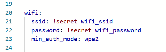
If you want, you can edit your YAML configuration files for your ESPHome devices to specify the WPA version to use. In the ‘wifi:‘ block, add ‘min_auth_mode: WPA2‘ underneath the network name and key, as so:
That will ensure that ESPHome always uses WPA2 on your devices, and will hide the warning. If your devices have ESP32 chips, and your router supports WPA3, you can add ‘min_auth_mode: WPA3‘ instead; this will offer better security. For more information, see the guide to the ESPHome Wi-Fi component.
Will ESPHome eventually phase out WPA2 support as well? Perhaps, but WPA3 is still pretty new – if your router is more than five years old then it may not support it. Maybe it will in another 15 years or so.
I quite like doing these round-ups of previously unblogged minor things at the end of each month. You can read what I wrote in October, and now here’s November:
Peter Pan-to time (oh no it isn’t)
We’re off to see Peter Pan at the Bradford Playhouse this weekend. It’s the annual pantomime from one of the local amateur dramatics societies, The Bradford Players. It also marks ten years since I helped backstage with Sleeping Beauty, a previous pantomime production. We don’t see a panto every year, but we know some of the cast and so we want to support them. Some tickets still available for the performances taking place today and tomorrow, but be quick.
The Bradford Playhouse is hosting another panto next month – Cinderella. By contrast, this is a professional production – several showings have already sold out but others have good availability. It’s cheaper than many mainstream theatres, and by booking to see it, you’re supporting smaller independent theatres.
I suck at soldering
In last month’s unblogged update, I mentioned how I was playing with a ESP development board to add Wi-Fi control to an existing non-smart device. In the end, I gave up, as my soldering skills just weren’t sufficient to keep the wires soldered to the contact points on the circuit board. If you’re interested, the device I was modifying was an Ikea Uppåtvind air purifier, and I was using this guide. To be fair, even if it had worked, I was using a much larger board than the D1 Mini recommended and so there’s no guarantee that I would have been able to re-assemble it anyway.
York Christmas Market
Whilst we were in York last weekend, alongside visiting York’s Chocolate Story, we also had a browse of York’s Christmas Market in Parliament Street. Even on a Sunday morning, it was very busy, and overall the city was the busiest I’ve seen it (remember, I grew up in York). Indeed, people have been complaining about how busy it is.
Christmas markets can be a bit hit-and-miss – I remember going to the Manchester Christmas market several years ago to find it was basically the same four stalls repeated across the whole city. York’s market is mostly local businesses, and it’s a good mix of food, drink and gifty things. We always buy a litre bottle of barbecue sauce from The Chilli Jam Man when we go.
Black Friday
I literally only bought two things on Black Friday this year, both from Amazon:
A 3 way plug with USB-A and USB-C(sponsored link). Christine has had one of these for a while and uses it daily; I’ve bought a second one because I want a charger for the bedroom that doesn’t have any LEDs on it.
The Actually Delicious One Pot Cookbook(sponsored link). This is the latest cookbook from Poppy O’Toole, aka Poppy Cooks, and it’s reduced to £10 (from £22) in their Black Friday sale. We already have her Potato Book and Slow Cooker books and use them both frequently.
Every now and again, we have an ‘away day’ at work. This time, it was hosted at Fountains Church, located on Chester Street in Bradford, pictured above. I’ve been in the building before it was a church, as it used to be three separate nightclubs: Revolution (the national chain of vodka bars), Walkabout (the national chain of Australian-themed bars) and Dr Livingstone’s, a nightclub themed around Dr David Livingstone, a colonialist and explorer. I visited them all regularly back when I was a student.
It was weird seeing the building now used as a place of worship.
A blue postbox in Manchester
On the way back from seeing Brains, Bogies and You, we walked past a blue postbox on Liverpool Road in Manchester. Normally, British postboxes are painted red (or occasionally gold), so this one is unusual.
Fortunately, a plaque on the side explains all. Originally, blue postboxes were more common, as they were used for air mail post. Nowadays, air mail no longer needs to be sorted separately from domestic post, and so all but one of these have been removed. The only remaining genuine blue air mail post box is outside Windsor Castle. This one is actually just a regular post box, painted blue.
This specific post box was painted blue because it sits next to what was the Manchester Aerospace Museum. This later became the Air and Space Hall of the Museum of Science and Industry, but was permanently closed a few years ago.
Playing with an ESP development board
Back in July, I picked up an ESP development board(sponsored link) to use as a firmware flasher. I’ve been experimenting with it, to try to add Wi-Fi control to an existing non-smart device. Let’s just say that I need more soldering practice, but I’m hoping to write more about it should I succeed.
Danny Boyle in Sowerby Bridge
I didn’t spot the film crew myself, but Danny Boyle has been filming scenes for his new film Ink in Sowerby Bridge, near where we live. It’s a biographical film about the early life of Rupert Murdoch. It’ll be interesting to see if we can recognise the filming locations when the film comes out.
I’ve also re-instated a number of old blog posts written in October 2015 from the Web Archive. These include Losing the Language of Love, which I quite enjoyed reading again, and several posts from a trip to London that month:
We also went to Crossness Pumping Station on that trip, but unfortunately my post about it was never indexed by the Web Archive and so it’s probably lost forever. It’s a shame – it’s a very interesting place. It’s not often that a sewage pumping station would be Grade I listed, and it’s only open on selected days of the year.
If you’re starting out with custom firmware for your existing devices, then I would still recommend Tasmota. It’s much easier to set up, as you install it first, and then configure it. There’s also a much more extensive repository of supported devices, so you shouldn’t need to do much manual tinkering once Tasmota is installed.
ESPHome, by contrast, requires you to configure it first, and then install it. Furthermore, rather than offering a web interface for configuring your devices, instead you have to do this in a YAML file. And then you have to compile the firmware specifically for your device and upload it.
That being said, ESPHome is much more powerful. You can build automations into it that run on the device itself, rather than through, say, Home Assistant. And as each firmware binary is compiled for each device, it’s much smaller, which allows for easier updates. On some Tasmota devices, you have to install a ‘minimal’ version of the firmware before you can upgrade. By contrast, with ESPHome, your device should be able to update directly to new firmware versions.
As you would expect, ESPHome integrates better with Home Assistant. Indeed, one reason for me changing to ESPHome is that the Tasmota integration takes a while to start up and is one of those slowing Home Assistant down. Firmware updates are also offered through Home Assistant, so you don’t need something like TasmoAdmin to manage firmware updates for multiple Tasmota devices.
Building the YAML file
I’m going to go through each section of the YAML file, to explain what it does, and why it’s necessary. Some of these are specific to the plugs that I’m using, and may not transfer to other devices.
Firstly, with Tasmota still running, open the Configuration screen and choose Template. This will give you a list of the GPIO pins, and what they currently do in Tasmota. You’ll need to note these, so that you can tell ESPHome what pins to use. On mine, these were the ones in use:
GPIO4 – LED
GPIO5 – Relay
GPIO13 – Button
The LED is the light on the smart plug, the relay is what controls whether the power is on or not, and the button is the physical button on the smart plug that controls the relay. Whilst the relay is the most important, to preserve the device’s full functionality, we need to tell ESPHome about all of them.
If you use the wizard in the ESPHome Device Builder, then these will have been created for you and filled out with whatever name you’ve chosen. The second block tells ESPHome that the device has an ESP8266 chip, and it’s a generic board. This was the default selection and seemed to work fine for me.
The logger means that the device will keep logs. It’s up to you whether you keep this in, but as I was coming up with this myself, I decided it would be best to help debugging.
Because I’ll be using this smart plug with Home Assistant, we need to include the ‘api:‘ section. Again, the ESPHome device builder should have filled out an API key here.
The ‘ota:‘ section allows for ‘over the air’ updates. This means that your device can update to new versions of ESPHome without needing to be plugged in to a device, either over USB or a UART connection.
In the ‘wifi:‘ section, this includes references to the ESPHome Device Builder’s secrets file which should have your Wi-Fi network SSID and password. If the smart plug can’t connect using these details, then, as a fallback, it’ll create its own access point. This is where we also need the ‘captive_portal:‘ section, which allows the user to select a Wi-fi network if the one we’ve pre-programmed can’t be found.
Web server
Next, we have this section:
web_server:
  port: 80
This is optional, but it creates a Tasmota-like web app that you can connect to. This will allow you to press the button on the smart plug, view the logs, and upload firmware. We don’t need it, but it partially replicates the functionality of the previous Tasmota firmware, and helps with debugging.
Binary sensor
This is the section that enables the hardware button on the smart plug to work:
We’re telling ESPHome that the button is attached to GPIO pin 13, and, when the button is pressed, to toggle the relay on or off. I’ve also added the ‘disabled_by_default: True‘ line so that it doesn’t show in Home Assistant.
Switch
Now, we need to configure the relay, and make it available to Home Assistant:
switch:
  - platform: gpio
    name: "Switch"
    id: "smartplug_relay"
    pin: GPIO5
    on_turn_on:
      - output.turn_on: led
    on_turn_off:
      - output.turn_off: led
    restore_mode: RESTORE_DEFAULT_ON
So, we’re telling Home Assistant that the relay is connected to GPIO pin 5. We’re also telling it to turn on the LED when the relay is turned on, and off again when it’s turned off. The ‘restore_mode: RESTORE_DEFAULT_ON‘ tells ESPHome what to do when the device boots up, perhaps after a power cut. I’ve set it to try to restore the status that it had before, but if it can’t, to turn the relay on.
LED
Here’s our final block, to tell ESPHome that there’s an LED
output:
  - platform: gpio
    pin: GPIO4
    inverted: true
    id: led
Again, we tell ESPHome that it’s connected to GPIO pin 4. The YAML code in the Switch section tells ESPHome when to turn the LED on or off.
So, now we have a YAML configuration file. This should be added as a new device in the ESPHome Device Builder.
The flashing process
The good news is that switching from Tasmota to ESPHome is easier than from the original Tuya firmware. You probably won’t have to get out a UART converter and cables, unless you accidentally brick your device. Instead, you just need to follow these instructions, which involve manually downloading the firmware binary, and then uploading it to Tasmota. When the device restarts, it’ll be running ESPHome instead.
A couple of weeks ago, I wrote about flashing Tasmota firmware onto some old Tuya smart plugs, using a USB to UART converter and some Dupont jumper cables. I also flashed Tasmota onto a Sonoff RF Bridge, which I’d bought to listen to doorbell presses. This meant that the RF Bridge would work with Home Assistant without needing a HACS integration or addon, and wouldn’t need to rely on cloud services to run.
However, inside every Sonoff RF Bridge there are two wolves chips with firmware. There’s an ESP8266 chip, which handles the Wi-Fi side of things, and an OBS38S003 chip which handles RF communication. I have the latest R2 v2.2 model; older ones have a different RF chip.
The default iTead firmware on the RF chip has been locked down to only support a limited number of RF messages. That’s fine if your device is supported, but my doorbell isn’t. So even with Tasmota installed, pressing the button my doorbell didn’t do anything as the RF firmware was programmed to ignore it.
Portisch RF fimrware
The OBS38S003 RF chip can be flashed with ‘Portisch’ firmware, which allows all RF messages to be received and decoded. However, whereas the ESP9266 chip has UART pins that don’t require any soldering to access, the OBS38S003 doesn’t support a UART bus. There are therefore two ways to get around this:
Modify the board using additional soldered cables and cutting some lines on the board
Using another circuit board, flashing firmware onto that, and then using the flashing board to flash the chip.
I went with option 2 – I don’t have a soldering iron to hand, and didn’t want to make a mistake and damage the board beyond repair. Instead, I bought this AZDelivery D1 NodeMCU Wi-Fi Development Board(sponsored link). There are a number of ‘D1’ boards out there – Wemos make the most well-known – but this was £7 and available from Amazon. Ironically this board also contains an ESP8266 chip.
Flashing the development board
To flash the D1 board, I needed to install two things:
I installed both, and then followed the instructions that came with the AZDelivery D1 board to set it up as a board in the Ardunio IDE. Next, I loaded the OnbrightFlasher into the Ardunio IDE and flashed it onto the D1 board. Make sure that use a micro-USB cable that supports both data and charging – a charging-only cable will power the device, but you won’t be able to connect to the D1.
Once the firmware is flashed, you can disconnect everything, put your Sonoff RF Bridge back together.
Testing the Portisch firmware
In Tasmota, open the Console and type in ‘rfraw 1‘ and press enter to enable Portisch. Then type ‘rfraw 192‘, and the device should beep. You can then type ‘rfraw 177′ and the Sonoff RF Bridge will go into ‘bucket sniffing’ mode – this will display the various codes being broadcast on the 433 MHz band. There’s more guidance on the Tasmota device page and RF commands section.
So, is my doorbell smart now?
The bad news is that, despite all this work, I haven’t been able to use the RF Bridge to capture my doorbell’s signals to turn them into actions in Home Assistant. The codes being sent by my doorbell seem to rotate, presumably so that only the receivers in my house respond and not someone else’s. And, the 433 MHz channel is also very noisy – there are lots of codes being sent by other devices like a frustrating game of Numberwang.
Basically, if I want to have a smart doorbell, I’m going to need to just buy an actual smart doorbell, aren’t I? At least I have an ESP development board to play with now.
Building on last week’s post about flashing smart plugs Tasmota, today I’m going to talk about other custom firmware that you can install on devices with an Espressif ESP chip. Tasmota is the most well-known, but whilst researching how to do the flashing, I’ve come across some others.
Tasmota
Obviously the first one I should mention is Tasmota. It seems to be the most well-used, with active development and lots of features. It’s designed to be used only on ESP32 and ESP8266 boards. Tasmota incidentally is an acronym which stands for Theo-Arends-Sonoff-MQTT-OTA and to this day Theo Arends remains the primary developer.
Recent Tasmota releases have included Matter support, albeit only on ESP32 chips which have more storage than ESP8266.
Notably, ESPurna only works on ESP8265 and ESP8266 chips, whereas Tasmota and ESPEasy also work on ESP32 chips, such as the one in the m5stack Atom Lite that I turned into a Bluetooth Proxy. Both ESPurna and ESPEasy use MQTT to communicate with other devices.
ESPHome
ESPHome is part of the Open Home Foundation, along with Home Assistant, and as such integrates well with Home Assistant. Unlike the other firmware tools here, ESPHome doesn’t use MQTT by default, although if you build your own firmware with ESPHome then you can add it as an optional extra. Instead, it communicates via Home Assistant’s API. This offers some advantages – it allows Home Assistant to install firmware updates for ESPHome devices. But if you were to switch from Home Assistant to another smart home platform, then you would either need to recompile the ESPHome firmware to add MQTT, or switch to one of the other firmware platforms listed here.
Another thing I’m less keen on about ESPHome is that you use a YAML configuration file to configure devices. I found Tasmota’s web-based interface much more user-friendly.
It’s worth noting that, as well as Espressif chips, ESPHome also works on RealTek RTL8710 and Beken BK7231 series chips too.
OpenMQTTGateway
OpenMQTTGateway is a more specialised firmware designed to make existing non-smart products work over MQTT. It’s best used with BLE (Bluetooth Low Energy), RD, Infrared and old fashioned Serial (RS232) devices. You can buy devices from Theengs which have the OpenMQTTGateway firmware already flashed.
As far as I can tell, OpenMQTTGateway just works on ESP32 chips.
OpenBeken
OpenBeken started out as a way of implementing a Tasmota-like experience on Beken BK7231 chips, but now supports a huge range of chips including ESP32 (but not some other Espressif chips like ESP8826) and RealTek RTL8710. It apparently works in a similar way to Tasmota, but I’ve yet to try it. I have one Tuya device with a BK7231 chip, but I haven’t yet been brave enough to try to flash it. Again, it uses MQTT to communicate with other devices.
Last year, I wrote about using a tool called tuya-convert to replace the firmware on my Tuya smart plugs. The firmware in question is Tasmota, which is an open source replacement firmware for devices with Espressif ESP chips. All my Tuya smart plugs have an ESP8266 chip, which can take custom firmware.
There are two ways of flashing Tasmota onto Tuya devices – an easy way, and a harder way.
There’s also a kind-of third ‘super-easy’ way, that I’ll mention towards the end.
tuya-convert – the easy way
I mentioned tuya-convert, which is a command line tool that exploits a vulnerability in older Tuya firmware to install Tasmota. You’ll need a computer such as a Raspberry Pi that has both Wi-Fi and Ethernet, and a smartphone. The tuya-convert tool then creates a hotspot that your Tuya devices can connect to when in pairing mode, and deploys the firmware wirelessly.
The key thing to emphasise here is that it only works with older firmware. Tuya patched the vulnerability in an update that came out some years ago, and indeed I’d already installed this on my smart plugs. That meant that tuya-convert could see the smart plugs, but couldn’t deploy the Tasmota firmware. So, I had to do it the hard way.
Using a UART converter – the hard way
As you may have guessed from the photo above, the only way I was able to flash Tasmota onto these smart plugs was by taking one apart, and using a USB to UART converter with some jumper cables. If tuya-convert doesn’t work, then this is what you’ll need to do. You’ll need the following:
Some Dupont Jumper cables – again, I bought these from AliExpress for £2.40. I picked up a big bag of male-male, female-female and male-female cables, but you only really need male-female cables if you want to save a few pence.
A computer with a USB port
I would also recommend the following:
Some electrical tape to hold things down
A USB extension cable
For the plugs that I was working with, I didn’t need a soldering iron, but some others may require it.
Disassembly and what’s inside
Firstly, it is very, very important that your smart plugs are not plugged into the mains while you do this, unless you want to burn yourself and/or your house down. We’ll be providing power via a different method, so make sure your device is not plugged in via the usual method. With my smart plugs, the positioning of the screws means it’s impossible for them to be plugged into the mains anyway.
Next, remove the screws from the plug. There were five on mine – the central one had to be removed first, and then the remaining four. Once that was done, I carefully separated the top and bottom of the housing.
The bottom part includes the high voltage AC circuitry. We’re not concerned with this and can leave it alone. What we’re interested in is the ancillary circuit board in the top part. It’s held in place by two small screws – you can remove these if you wish, but you can easily access the five pin holes that we need with the board still screwed in place.
The pin holes are as follows, with the first closest to the edge:
RX – data in
TX – data out
GND – ground
GPI00 – the pin hole that puts the smart plug into flashing mode
5V – the 5 volt power input pin hole
Normally, ESP chips work at 3.3 volts, but there’s a converter chip elsewhere on the circuit board for these specific smart plug. Yours may be different, so check first to see if it’s 3.3 volts or 5 volts. The UART to USB converter that I have offers both, so we’ll use five volts for this.
Connecting the wires
Firstly, make sure your USB to UART converter is not plugged in to the computer. You’ll need to get your Dupont cables and connect them from your converter to the board. The pins on the converter should be labelled, so you need to connect them as follows:
From RX on the board to TXD on the converter
From TX on the board to RXD on the converter
From 5V on the board to 5V on the converter
From bothGND and GPI00 on the board to GND on the converter
For this last one, I used three cables – two male-male cable from each of the GND and GPI00 ports on the board, and one female-male cable from the GND port on the converter – and then taped the pins at the end of the wires together. If it helps, there’s a standard wiring diagram on the Tasmota Getting Started page – although we’re connecting one additional wire (GPI00).
Getting read to flash Tasmota
Now that we’ve linked the converter to board, we can do the fun bit – flashing the device. There are several ways you can do this, of which I would recommend two:
Tasmotizer – this is a simple Windows program for flashing. The key advantage is that it can optionally download and backup the previous firmware, just in case you want to restore it later.
Tasmota Web Installer – this allows you to install Tasmota through your web browser, using WebSerial. As it stands, only desktop versions of Chrome, Edge and Opera support it, so you can’t use Firefox or Safari.
Personally, I had a better experience with the Web Installer, so this is what I used. Once you’ve opened your flashing tool, plug the USB to UART converter into your computer and then click ‘Connect’. Your browser will ask for your permission to link the web page with the COM port created by the converter, so you’ll need to grant permission.
Note: sometimes the COM port wouldn’t show for me in the browser. If this happens to you, try opening Device Manager, if using Windows, to ensure that the driver has installed correctly. If not, asking Device Manager to simply update the drivers should be enough. I had the most success if I opened the web page, connected the USB to UART converter and then clicked ‘Connect’ in that order.
If all is well, the web flasher will connect to your device, erase the existing firmware and then upload Tasmota. It’s a quick process – the binary file for Tasmota version 15 is only 655 kilobytes, so it’ll only take a couple of minutes at most.
If you get a connection error, try swapping the RX and TX cables over and then try again, and make sure that the light on the circuit board isn’t on or flashing. If the light is on, it’s a sign that you’ve not connected the GPI00 pin correctly.
Assuming that the flashing worked, you can take the jumper cables out and reassemble your device and plug it back in to the mains.
Configuring Tasmota
So, now that your device has been flashed, you need to configure Tasmota on the device. Get your phone out, and go to Wi-Fi settings. You should see a new Wi-Fi hotspot called ‘tasmota-something-something’, where the somethings are an alphanumeric string – connect to it. A hotspot login box should appear – if not, go to http://192.168.4.1/ in your phone’s web browser.
The first step is to connect Tasmota to your Wi-Fi network. Choose the network, or type it in, and provide the password. Tasmota will then connect, and, if successful, will redirect to its new IP address which it’ll display on screen. I suggest making a note of this.
You’ll now need to navigate to Tasmota’s new IP address in a web browser – you can do this on any device, not just your phone. The first thing we need to do is tell Tasmota what kind of device it has been installed on. The easiest way to do this is with a Template, and there are a huge range of templates listed here. I couldn’t find an exact match for mine, but the closest was this one, which gave me the following template code:
To paste this template into Tasmota, I used this guide. From the Tasmota home screen, I clicked ‘Configuration’, then ‘Configure Other’, and pasted the whole string into the ‘Template’ field at the top. Tick the box that says ‘Activate’, and then the green Save button at the bottom. Tasmota will restart, and then you’ll find that your smart plug now works. Huzzah!
Integrating Tasmota with Home Assistant
If you want your newly Tasmotised smart plug to appear in Home Assistant, then there are a couple more steps that we need to take. Tasmota communicated with other devices using MQTT, so if you don’t already have MQTT set up in Home Assistant, you’ll need to do this. The easiest way is to install the Mosquitto addon; this will then suggest the MQTT integration for you.
Next, we need to create a user account for Tasmota to use with MQTT. In Home Assistant, open Settings, and then People. At the top, select ‘Users’, and then click the blue ‘add user’ button. Give them a username and password, and then save these details somewhere safe for the next step.
Back to Tasmota. Firstly, we need to change a setting to allow Home Assistant to automatically discover your new Tasmota device. From the Tasmota home screen, choose ‘Console’, and input the following command:
SetOption19 0
Press enter. Next, go back to the Tasmota home screen, and into ‘Configuration’ again. Select the ‘Configure MQTT’ option. In the first box, you’ll need to enter the IP address or local hostname for your Home Assistant installation. If you use Home Assistant OS, this is most likely to be ‘homeassistant.local’.
Next, we’ll need to enter the username and password for the MQTT account we created earlier. The rest of the fields can be left with their default values, unless you want to customise the name.
Back to Home Assistant. If this is your first Tasmota device, then you should receive a notification that a new Tasmota device was found, and that you need to install the Tasmota integration. Do this, and your device will now be available. If you add any further devices, these will automatically appear in the Tasmota integration once their MQTT settings have been configured.
And that’s it. You should now be able to control your devices without needing to use Tuya’s cloud services.
The super-easy way – pre-flashed Tasmota devices
If you don’t already own a suitable smart plug, but want to use Tasmota, my advice would be to buy a smart plug with Tasmota already flashed. Local Bytes sell pre-flashed Tasmota smart plugs, so you can skip the disassembly and flashing sections of this guide. Alternatively, try eBay, where these plugs can also be bought pre-flashed.
That being said, I’m pleased to have been able to flash Tasmota on these smart plugs. I’m currently only using one of them, but I’ve been able to give them a new lease of life with about £5 of materials and an hour or so of my time. Indeed, the spare ones may well end up on eBay in due course for someone else to use. It’s far better than letting them become yet more e-waste.
What’s next
Last year I bought a Sonoff Wi-Fi RF Bridge, but was disappointed that it wouldn’t work the way that I expected it to. And getting it to work with Home Assistant was a bit of a pain, requiring a custom integration from HACS or an addon. I’ve already installed Tasmota on it, so it too has local control, and I’m looking at flashing the RF chip with a different custom firmware to make it more useful. That will probably require soldering and is for another future blog post, however.