I recently bought a GeekMagic SmallTV Pro (sponsored link), which is a small, always-on desktop screen that runs on USB power. Out of the box, it can display the weather, a small range of photos, share prices and cryptocurrency prices. However, I’ve connected it up to Home Assistant to display a dashboard.
There are two varieties of the GeekMagic SmallTV – the ‘Ultra’ and the ‘Pro’. The ‘Ultra’ is actually the more basic model, and isn’t available to buy on Amazon. Both types are available on AliExpress, however. Inside, the ‘Ultra’ model has an older ESP8266 chip, whereas the ‘Pro’ has the newer and more powerful ESP32 chip. Both offer a roughly one inch square screen and connect using USB-C.
Setting up the GeekMagic SmallTV
Like many ESP-based devices, when you first plug the GeekMagic SmallTV in, it’ll create its own Wi-Fi access point. Connect to this on your smartphone, and it’ll pop up a captive portal where you can select your home Wi-Fi network and provide the password.
It’ll then reboot and connect to your home network, and will flash its new IP address whilst booting. You can then go to http://[IP Address]/ in your web browser to configure settings. Note that the cheaper ‘Ultra’ model doesn’t support stocks or cryptocurrency tracking.

Integration with Home Assistant: Method 1
There are two ways that you can integrate your GeekMagic SmallTV with Home Assistant. Method 1 is the method that I have used, as it’s less invasive and leaves the stock firmware intact.
Inside Home Assistant, open HACS, and add the above-linked GitHub page as a repository. You can then install the GeekMagic integration – once done, reboot, and then add your device on the Integrations panel.
How this integration works is by generating an image of several dashboard entities, which it then pushes to your device. You should notice a new ‘GeekMagic’ section on the main sidebar that allows you to open the dashboard editor – click this, and you’ll be able to create a new dashboard.
There are multiple layouts available, allowing you to display between one and nine entities. Theoretically, any entity in Home Assistant can be added. Personally, I’ve added the date and time, my solar battery status, the weather, my car’s charge status, how much energy is being generated by my solar panels, and my dishwasher’s progress through a cycle. Most of these are ‘gauge’ displays in the ‘ring’ style, so as well as showing the percentage, the ring gives a clearer visual indication of progress. This is good on such a small screen.
Once set up, the integration pushes a new image to the GeekMagic SmallTV device on a regular basis. I found that I had to remove all of the other images, and set it to change every 10 seconds, to keep the dashboard showing and updated.
Integration with Home Assistant: Method 2
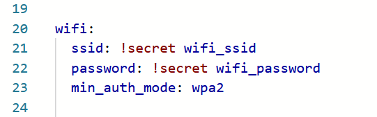
If you clocked that these devices have ESP chips earlier, then it won’t surprise you that people have installed ESPHome on them. This involves replacing the stock firmware with ESPHome, which is easy to do – the web interface on the stock firmware has a firmware upload tool that should accept an ESPhome binary. I say should because I haven’t tried it personally.
If not, then the good news is that this device is easily dismantled – there are a couple of standard screws on the bottom. Inside, the printed circuit board includes GPIO pin holes for its UART interface. That may also help if you accidentally brick the device and need to replace the firmware manually.
I haven’t gone down this route as yet, as it takes more work. You would have to specify what to display on the screen in the ESPHome YAML configuration, and you’ll lose all the other functionality provided by the stock firmware. Also, be aware of various copycat devices with slightly different chips; they’ll almost certainly still run ESPHome but you may need to amend the configuration slightly.
I quite like my GeekMagic SmallTV Pro – it’s handy to be able to track key entities in Home Assistant without having to open my phone or look at the full dashboard. And it’s sufficiently low power that it can run all the time.